Nullam dignissim, ante scelerisque the is euismod fermentum odio sem semper the is erat, a feugiat leo urna eget eros. Duis Aenean a imperdiet risus.
Nullam dignissim, ante scelerisque the is euismod fermentum odio sem semper the is erat, a feugiat leo urna eget eros. Duis Aenean a imperdiet risus.
 author
Analysis of the Mechanism and Standardized Troubleshooting for Excavator Stalling Faults
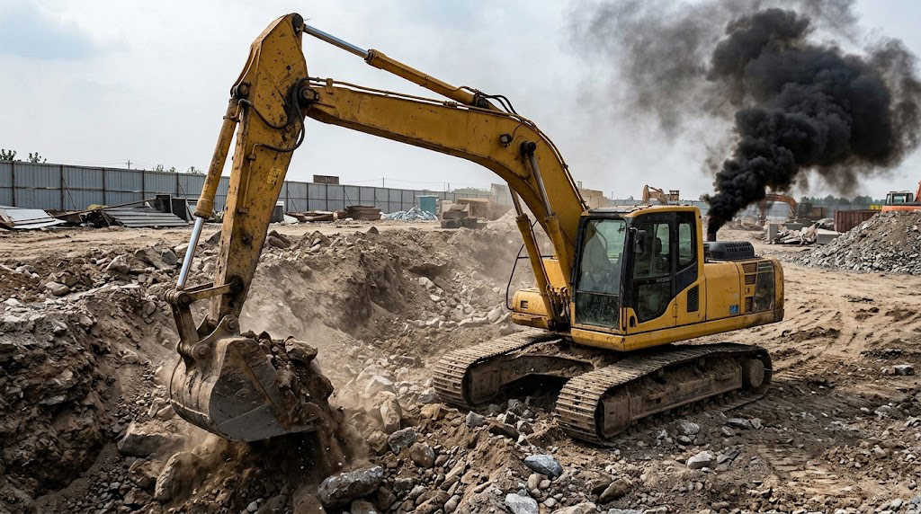
During operation,when an Excavator experiences engine stalling ,the fundamental cause is that the torque currently absorbed by the hydraulic main pump exceeds the maximum effective torque the engine can deliver at that particular speed.At normal working situation,when the system encounters a hard object OR experiences a sudden pressure surge,the hydraulic control Mechanism automatically reduces the swash plate Angeles of the main pump(decreasing displacement),thereby ensuring that the Power absorbed by the main pump does not exceed the engine’s limit.
Three Core Causes of Excavator Stalling and Component Analysis
Power Source Degradation on the Engine Side
The engine itself cannot deliver rated torque due to restricted fuel supply or air intake. On the fuel side, a clogged diesel filter, excessive water accumulation in the water separator, insufficient fuel transfer pump pressure, or air ingress into the fuel lines will cause fuel delivery to lag under high load, typically resulting in stalling with little or no black smoke. On the intake and turbocharging side, a severely clogged air filter, worn turbocharger blades, or cracked/leaking inter cooler connecting hoses lead to insufficient air intake and incomplete diesel combustion; the typical symptom is dense black smoke and severe speed drop as soon as load is applied. In addition, worn high-pressure common-rail injectors that leak pressure or atomize poorly, or rail-pressure sensors that trigger pressure-limiting protection, will also directly weaken the engine’s effective power output.
Excessive Main-Pump Load Caused by Hydraulic Pump Regulating Mechanism

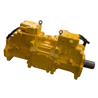
When engine power is normal but the main pump (for example, Komatsu PC300-7 hydraulic pump, part number 708-2G-00024, or PC400-7 hydraulic pump, part number 708-2H-00450) cannot promptly reduce the swash-plate angle under high pressure, both displacement and pressure remain high simultaneously. Because power equals pressure multiplied by flow, the simultaneous high values instantly overload the engine. In a tandem piston main-pump structure, the front and rear pumps are each fitted with their own regulators, with a proportional solenoid valve in between; these components jointly perform dynamic adjustment of the swash-plate angle. If the power-control (PC) valve spool or servo piston inside the front or rear pump regulator becomes stuck in the “large-displacement” position by metal debris or varnish in the hydraulic oil, the swash plate cannot return when external load increases. Likewise, if the main relief valve on the multi-way control valve (for example, Komatsu PC200-8MO control valve, part number 723-46-29100) has been manually set too high or its spool is stuck, the system cannot relieve pressure properly under extreme load, allowing system pressure to far exceed the rated value (normally 32–35 MPa). Frequent overload during heavy digging converts engine power directly into heat. In addition, abnormal pressure in the auxiliary pilot circuit supplied by the rear gear pump can deprive the regulator servo mechanism of sufficient driving force to reduce the swash-plate angle.
Misjudgment Caused by Electronic Control and Sensor Signals
When the proportional solenoid valve on the main pump suffers from coil aging, spool wear/sticking, or loose connectors, it cannot output the correct secondary pilot pressure according to the commands from the ECU/pump controller. On the other hand, if the engine speed sensor or main-pump high-pressure sensor drifts or becomes inaccurate, the controller cannot detect that the engine has already slowed down and therefore fails to command the proportional solenoid valve to reduce displacement, ultimately causing severe stalling or premature system failure.
On-Site Standardized Troubleshooting and Repair Procedure (Simple to Complex)
Before inspecting hydraulic lines or engine components, strictly observe high-pressure and high-temperature safety precautions: before checking or removing the main-pump regulator or proportional solenoid valve, fully lower all working devices to the ground, shut off the engine, and relieve residual pressure and tank back-pressure through the pilot levers. Never remove hydraulic components while the engine is running or lines are under pressure, to avoid personal injury from high-temperature, high-pressure oil spray.
After safety preparations are complete, the first step is a roughly 5-minute preliminary diagnosis. Start the machine and set it to high-idle working mode; test both single functions (e.g., arm only) and combined functions while observing exhaust color and speed drop. When stalling under load is accompanied by dense black smoke, first remove and clean the air filter, check the turbocharger and inter cooler silicone hoses for cracks or leaks. If all functions produce black smoke and stalling, the proportional solenoid valve may have failed, causing overall power overload. When stalling occurs under load with no black smoke (or only light/white smoke), drain water from the water separator, replace the primary and secondary diesel filters, and bleed air from the fuel lines. Regarding the range of affected functions: if boom, arm, travel, swing, and all other functions stall, focus on the diesel supply system, main intake/turbocharging system, or the overall pump proportional solenoid valve (EPC). If only one side of the machine stalls, the engine is normal and the fault is concentrated in the corresponding main-pump regulator (front or rear) or main control valve. If only a single function stalls (e.g., arm fully extended under load), both the engine and main pump are normal; the fault lies in the overload relief valve of the corresponding multi-way valve section being set too high or its spool being stuck.
The second step is a roughly 15-minute basic fuel and air circuit check. Open the drain valve at the bottom of the water separator to drain water; inspect the primary and secondary diesel filters for varnish or contamination; simultaneously check the air filter and the silicone hoses from the turbocharger to the inter cooler for cracks or loose clamps. After replacing filters or tightening lines, test the machine: under normal conditions, no-load rapid acceleration should be responsive, and engine speed drop under load should remain within 150–200 rpm. If the basic fuel and air circuits are normal but the fault persists, proceed to the third step—a roughly 10-minute electronic control and pressure-parameter diagnosis. Enter the service diagnostic mode on the cab monitor, display front/rear main-pump pressures and proportional-solenoid-valve drive current, then perform an arm relief operation (full stroke under load). Observe whether pressure exceeds the factory upper limit (normally 32–35 MPa) and whether the solenoid current dynamically adjusts with engine speed drop (normally in the approximate range of 300–800 mA according to load). If current remains fixed, the solenoid circuit or controller board is at fault; if both pressure and current are normal yet stalling continues, proceed to mechanical disassembly.
The fourth step is a 30-minute-or-longer cleaning and testing of hydraulic control components. After shutting down and relieving tank back-pressure, remove the proportional solenoid valve from the main pump, clean the spool with carburetor cleaner, and check that the spool slides freely; the front/rear pump lines or connectors can also be swapped to verify whether the fault transfers. If the solenoid valve is normal, disassemble the pilot spool and PC valve spool inside the front/rear pump regulators, flush internal sludge and fine metal debris with carburetor cleaner, check for stuck metal particles or broken return springs, and gently push the spool with a screwdriver to confirm smooth spring return before reinstalling and retesting. During repair work, never perform large-scale disassembly without careful analysis of the root cause. When replacement parts are required, inspect new components for appearance and performance before installation, use genuine original-specification parts and high-strength bolts, tighten to the specified torque and sequence, thoroughly flush the hydraulic system, and replace old filters promptly to prevent residual hard abrasive particles from re-entering the main pump and valve group and causing sticking or premature wear.
YIKAN KOMSU Manufacturing Standards and Exhibition at bauma China in Shanghai
To break the cycle of hydraulic-system degradation and power imbalance caused by oil contamination, poor machining, or parameter mismatch, selecting a supplier with strict quality control and manufacturing standards is essential. YIKAN KOMSU is an integrated industrial and trading enterprise with more than 20 years of professional experience in hydraulic systems, hydraulic piping, and engine components. It focuses on R&D, production, and global trade, providing customers with end-to-end hydraulic solutions ranging from component selection, valve-block design and manufacturing, tank and piping fabrication, to system assembly and testing. In the manufacturing process, YIKAN KOMSU has established an extremely rigorous independent quality-control system: core production steps include spectral analysis of raw materials and high-precision CMM inspection after CNC machining. Especially during hydraulic-component assembly, the workshop enforces the highest cleanliness standards, and every product undergoes final functional and durability testing. Thanks to a flexible production line capable of efficiently handling diverse order volumes, YIKAN KOMSU achieves cost optimization and rapid delivery while ensuring complete product lifecycle traceability, supplying customers with robust components that fully match system specifications and whole-machine stability solutions based on deep technical expertise.
As an important component manufacturer and supplier in the global construction-machinery aftermarket, YIKAN KOMSU will participate in bauma China in Shanghai (booth number E2-149). At the exhibition, the company will showcase hydraulic main-pump assemblies, main-pump regulators, main control valve blocks, proportional solenoid valves, high-pressure hydraulic lines, and core engine components for various excavators and heavy-duty equipment. On-site technical teams will provide diesel-hydraulic power-matching consultation, sample process demonstrations, and customized global supply-chain connection services for international buyers and construction-machinery customers.
Frequently Asked Questions (FAQ)
How can exhaust color be used to quickly distinguish whether excavator stalling is a fuel-circuit or air-circuit problem?
Stalling under load accompanied by dense black smoke indicates insufficient air intake and incomplete diesel combustion; prioritize checking for a clogged air filter, worn turbocharger, or cracked/leaking inter cooler connecting hoses. If stalling occurs with no black smoke or only light smoke, fuel delivery is lagging under high load; prioritize checking for clogged diesel filters, excessive water in the water separator, or air in the fuel lines.
Why does the excavator stall only on one side of the machine or during a single function while other functions remain normal?
Stalling only on one side indicates that the engine is normal and the fault is concentrated in the corresponding main-pump regulator (front or rear) or main control valve. If only a single function stalls (e.g., arm fully extended under load), both the engine and main pump are normal; the fault lies in the overload relief valve of the corresponding multi-way valve section being set too high or its spool being stuck.
How can the cab monitor be used to determine whether stalling is caused by a proportional solenoid valve electronic-control fault?
Enter the service diagnostic mode on the cab monitor. While performing an arm relief operation under load, observe main-pump pressure (upper limit normally 32–35 MPa) and the drive current of the proportional solenoid valve (PC-EPC). Under normal conditions the current should dynamically adjust within approximately 300–800 mA as engine speed drops under load. If the current remains fixed or is 0 mA, the solenoid circuit or controller board is at fault.