Pas de dignité, devant le scélérisque c'est la haine euismod fermentum sem sempre l'is erat, a feugiat leo urna eget eros. Duis Énée Une coupe de cheveux pour rire.
Pas de dignité, devant le scélérisque c'est la haine euismod fermentum sem sempre l'is erat, a feugiat leo urna eget eros. Duis Énée Une coupe de cheveux pour rire.
 auteur
Comprehensive Testing Standard for Hydraulic Components of Excavators
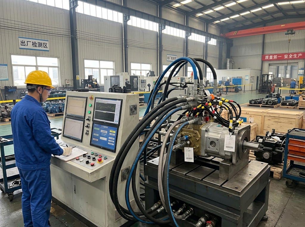
The reliability of hydraulic pump,main control valve,walking device,and rotation device decides equipment performance. If the components that you purchase are installed in the machine without strict technical inspection,they maybe cause failures due to internally hidden defects.So,before the hydraulic core component for excavator are used,it must be tested by simulating the extreme loads of the equipment under actual Working conditions,all performance parameters can be comprehensively verified.
Hydraulic component testing items and performance calibration
On the dedicated hydraulic comprehensive testing platform, the testing focuses respectively on the working mechanisms of the main pump, main control valve and motor, with particular emphasis on displacement control, precise throttling and anti-load torque output.
The tests for the hydraulic main pump (such as the Komatsu PC300-7 hydraulic main pump, part number 708-2G-00024; or the PC400-7 hydraulic main pump, part number 708-2H-00450) primarily cover volumetric efficiency and flow calibration. That is, at the rated speed of the equipment, apply no-load, medium-pressure, and high-pressure step loads to the pump, and measure the actual output flow at each stage.If the flow rate significantly decreases under high pressure, it indicates that the internal clearance of the pump is too large. The next step is the variable regulation logic test (PC/LS control). The test bench simulates the actual working conditions of the excavator and inputs load-sensitive and constant-power lead pressure signals to the pump, while monitoring the response speed of the swash plate angle and the flow regulation curve in real time. This ensures that the main pump can quickly reduce the flow when the external load suddenly increases, preventing the supporting engine from stalling due to overloading. At the same time, internal leakage and temperature rise detection must be carried out. During full-load operation, the amount of oil returned per minute from the pump housing’s oil drain port is measured. If the internal leakage exceeds the standard and is accompanied by abnormal oil temperature rise, it directly indicates that there is early wear or processing defects in the internal piston, sliding shoe, or flow distributor plate.
Next is the variable regulation logic test (PC/LS control). The test bench simulates the actual working conditions of the excavator by inputting load-sensing and constant-power pilot pressure signals to the pump, and real-time monitors the response speed of the swash plate inclination angle and the flow regulation curve, ensuring that the main pump can rapidly reduce flow when external load suddenly increases, preventing the matching engine (such as SAA6D102E-2) from stalling due to overload.
At the same time, internal leakage and temperature rise detection must also be performed. Under full-load operation, the oil return volume per minute from the pump case drain port is measured. If internal leakage exceeds the standard and is accompanied by abnormal oil temperature rise, it directly reflects early wear or unqualified machining of internal plungers, slippers, or valve plates.
Main Control Valve Testing
For the main control valve (multi-way valve, e.g., Komatsu PC200-8MO main control valve assembly, part number 723-46-29100), testing includes high-pressure sealing and external leakage testing. By plugging all working oil ports and applying extreme oil pressure exceeding the system’s rated maximum pressure, the valve body casting is strictly checked for the presence of tiny sand holes, and whether the various mating surfaces and seals are leaking oil.
In the fine control and reversing tests, the test bench inputs low-pressure pilot control oil of different gradients to the pilot oil ports, measures the linear displacement of the main spool and the corresponding flow output curves of the oil ports, thereby verifying whether the design of the micro-throttle grooves on the spool meets the standards. This directly determines the smoothness of fine movements after the excavator is installed.
In the internal leakage test, when the spool is in the neutral position or a specific working position, pressure is applied to the main inlet port, and a measuring cup or high-precision flow meter is used to measure the tiny amount of oil leaking from the working oil ports or return ports. This data is used to directly inspect the precision fit tolerance between the main spool and the valve body bore.
Finally, there is the relief valve pressure calibration. By sequentially triggering the main relief valve and the secondary relief valves of each action oil port, the opening and closing pressure points are calibrated to ensure precise pressure relief when the actuators encounter hard resistance.
Travel and Swing Motor Testing
Testing for travel and swing motors focuses on torque and brake sealing. In the starting torque and mechanical efficiency tests, the test bench applies resistance load and measures the minimum starting pressure required for the motor to begin rotating and the output torque, to ensure that the equipment has sufficient travel and swing force under muddy or heavy-load conditions.
In the parking brake and stalled internal leakage tests, the opening pressure of the hydraulically released brake is first tested. Then, under the condition of locking the motor output shaft, high-pressure oil is injected, and the internal leakage of the case is measured to accurately determine the static pressure sealing performance of the motor cylinder block and valve plate.
Standardized Testing Process of the Hydraulic Comprehensive Test Bench
To ensure that every factory hydraulic component can withstand the extreme loads in actual construction operations, the full-condition hydraulic comprehensive test bench strictly executes testing and sampling verification according to six standardized physical steps.
Installation and Initial Break-in Testing
Technicians fix the hydraulic pump or motor on the test bench driven by a high-power motor and connect the inlet, high-pressure outlet, and case drain lines. First, high-cleanliness hydraulic oil is circulated under low pressure and low speed to exhaust air from inside the component, allowing the internal precision rotating components to undergo preliminary lubrication and break-in. At the same time, sensors or auscultation are used to check for abnormal mechanical friction noise.
Pressure Resistance and Sealing Test (Pressure Test)
By adjusting the high-pressure loading valve of the test bench to simulate the huge external resistance when the excavator encounters hard rock, the system pressure is stepwise increased to the component’s rated maximum relief pressure (typically between 35 MPa and 40 MPa for Komatsu heavy excavators). While maintaining high pressure, the pump housing, joint surfaces, and main shaft seal areas are checked for hydraulic oil leakage, comprehensively verifying the structural strength of the casting.
Flow and Volumetric Efficiency Testing
Under conditions simulating the engine’s rated speed (e.g., 1950 rpm), data from high-precision flow meters are read at no-load, medium-pressure, and full-load pressure points respectively. The actual output flow is compared with the designed theoretical flow to calculate volumetric efficiency. If the flow attenuates significantly under high pressure, it indicates that the internal fit clearances do not meet the standards. Such non-conforming products will inevitably cause slow movements of the excavator after installation.
Variable Regulator Logic Testing for Main Pumps
For the complex displacement regulators on the main pump (such as PC constant-power valves and LS load-sensing valves), the test bench inputs different pilot control pressures to the regulator and real-time monitors the change in the pump’s swash plate inclination angle and the flow response time, ensuring that the pump can rapidly reduce flow when external load increases, preventing the engine from “stalling” or dropping speed due to overload.
Internal Leakage and Temperature Rise Monitoring
During full-load operation, the test bench separately measures the volume of hydraulic oil flowing out from the pump case drain port. Internal leakage is a core indicator reflecting the machining accuracy and wear condition of internal parts such as plungers, slippers, and valve plates. During the test, oil temperature is continuously monitored, because excessive internal leakage or abnormal friction will convert hydraulic energy into additional heat, leading to abnormal oil temperature rise. This is also a typical symptom after the hydraulic system is damaged by contamination.
Durability and Fatigue Testing.
This step is usually conducted as batch sampling inspection or new product type verification. The test bench automatically runs a preset alternating load program, causing the system to switch frequently between low pressure and ultra-high pressure, thereby simulating the severe pulse-type impacts generated by the excavator during continuous digging, swinging, and dumping, and continuously running for tens to hundreds of hours, thoroughly verifying the fatigue resistance life of the components.
YIKAN KOMSU Manufacturing Quality Control System and Exhibition at bauma China in Shanghai
For hydraulic core components to successfully pass the above rigorous extreme bench tests, strict control of metallurgical materials, machining tolerances, and assembly cleanliness in the front-end manufacturing process is indispensable. YIKAN KOMSU is an integrated industry-and-trade enterprise with more than 20 years of professional experience in the fields of hydraulic systems, hydraulic piping, and engine components. It focuses on R&D, production, and global trade, providing customers with end-to-end hydraulic solutions ranging from component selection, valve block design and manufacturing, oil tank and piping fabrication to system assembly and testing.
YIKAN KOMSU has established an extremely strict independent quality control system. Its core production process includes not only spectral chemical composition analysis of initial raw materials, but also micron-level inspection of part fit clearances and geometric tolerances using a coordinate measuring machine (CMM) after high-precision CNC machining. Especially during the assembly of hydraulic components, the workshop implements the highest level of cleanliness control to eliminate early abrasive particle contamination. Subsequently, each product undergoes final functional testing, pressure calibration, and durability testing on a dedicated comprehensive test bench. With a flexible production line capable of efficiently handling diversified order volumes, YIKAN KOMSU not only achieves cost optimization and rapid delivery, but also realizes complete traceability throughout the product life cycle, ensuring that every hydraulic component purchased by customers has reliability matching the OEM specifications.
As an important supplier of hydraulic and engine components in the global construction machinery aftermarket, YIKAN KOMSU will participate in bauma China in Shanghai (Booth No.: E2-149). At the exhibition site, the company will focus on displaying Komatsu series hydraulic main pump assemblies, main control valve assemblies, swing and travel motor components, precision rotating friction pairs, and high-pressure piping that have undergone full-process bench calibration testing. On-site engineering and technical teams will provide global buyers and equipment managers with services such as interpretation of bench test parameters, selection matching, and global trade docking.
Foire aux questions (FAQ)
Q: How to determine whether the internal fit clearances of a hydraulic main pump are qualified on the hydraulic comprehensive test bench?
A: It is mainly determined through volumetric efficiency testing and internal leakage detection. Under simulated engine rated speed and 35 MPa high-pressure load, if the actual output flow shows significant attenuation compared with the theoretical flow, or the oil return volume per minute from the case drain port exceeds the standard and is accompanied by abnormal temperature rise, it indicates that the fit clearances of the plungers, slippers, or valve plates are too large and the machining is unqualified.
Q: Why must the main control valve be subjected to extreme oil pressure above 40 MPa and fine control testing during factory testing?
A: Applying oil pressure above 40 MPa, which exceeds the system’s rated maximum pressure, is to check whether the valve body casting has tiny sand holes and whether the sealing mating surfaces are leaking oil. Inputting PPC pilot oil of different gradients to test fine control is to verify the machining accuracy of the micro-throttle grooves on the main spool, ensuring the smoothness of the excavator’s fine movements after installation.
Q: How does the pre-delivery durability and fatigue testing simulate the real severe working conditions of excavators?
A: The test bench automatically runs a preset alternating load program, allowing the system to switch frequently between low pressure and ultra-high pressure, and continuously runs for tens to hundreds of hours. This simulates the severe pulse-type hydraulic impacts borne by the excavator during actual continuous digging, swinging, and dumping operations, thereby verifying the fatigue resistance life of the components.